
Past Projects
Minimally Actuated Legged Millirobots
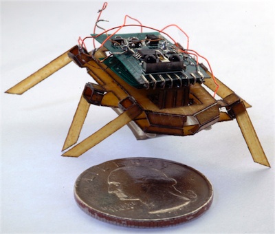
Building autonomous, legged millirobots presents unique challenges. Robotic designs must be highly integrated in order to satisfy the myriad constraints that accompany this difficult size scale. Using a novel process that incorporates compliant mechanisms, high strength/lightweight composites, shape memory alloy actuators, and low complexity electronics, we have developed the Robotic Autonomous Crawling Hexapod (RoACH) pictured to the right. Its unique parallel kinematics and lightweight, articulated skeleton combine with high power density actuation and reduced complexity power and control electronics to create a 2.4 gram robot capable of steerable autonomous locomotion at a rate of 1 body length/sec for up to 9.5 minutes on a single charge.
Rapid Prototyping Folded Robots
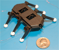
Designing and building robots at the millimeter scale is difficult. With minimum feature sizes on the order of 100μm, millirobots require precise machining techniques, novel fabrication approaches, and careful final assembly by hand. The smart composites microstructures paradigm is enabling technology for integrated millirobotic systems at small scales, but it can be mimicked inexpensively at larger scales (2-5X) for prototyping articulated, folded robots. This project makes use of inexpensive materials and fast fabrication processes to produce a fully functional robot prototype in about 1 hour. For more information, watch this YouTube video tutorial or read the paper titled, Fast scale prototyping for folded millirobots.
Subdivision Surfaces for Machining
Our robotics research often involves novel approaches to design and fabrication, and these interests have at times spilled over into the more "traditional" area of manufacturing that is subtractive machining. Freeform surfaces are attractive to designers because they provide limitless design possibilities especially for products like consumer appliances or electronics. In recent years designers have been pushing the limits of surface modeling tools to create beautiful, organic, freeform surfaces in everything from vacuums to portable music players. For the engineer, however, the freeform surface is difficult to express mathematically and cumbersome to work with when the time comes to produce the physical artifact (usually through some plastic molding process). The purpose of this work was to attempt to use a unified representation (adaptive subdivision surfaces) for both design and manufacture, and, in the process, reduce the time required to manufacture the part as well as improve the overall final part quality. To this end, we developed a tool that uses subdivision to generate a tool path for machining a freeform surface to within a specified surface finish. The tool is written in C++ and uses OpenGL and Qt for the GUI. The work is still in progress, but we hope to be able to make the source code and example files available in the not too distant future.

The Moebius Gear
The Möbius gear isn't directly related to robotics but came about as a course project for Procedural Solid Modeling taught by Professor Carlo Séquin at Berkeley. I was immediately intrigued by the curious combination of the Möbius mathematical surface popularized by M.C. Escher and functional mechanical gear elements. After some time staring at and puzzling over this image, I convinced myself that this mechanism is indeed possible and that with the right tools, a functional prototype could be built. Using a combination of the Scene Language for Dynamic Environments (SLIDE), developed at Berkeley, Tcl, Python, and Solidworks, I was able to create models of the constituent components. The base was fabricated on a Stratasys fused deposition (FDM) machine and took approximately 86 hrs. to finish. The “spur” gears were molded in silicone rubber using a two-part mold printed on a 3D Systems wax deposition machine (ThermoJet). The central Möbius strip was also molded using molds printed on the 3DS machine. The Möbius strip was molded as a single linear strip then twisted and the ends were rejoined in a “guiding” mold and additional rubber was poured into that mold to bond the two ends together and form a single continuous ring. The end result is a functional prototype, but rotating the middle ring without having the blue gears pop out is a little tricky. If you’re so inclined you can download a description of the entire process from modeling to fabrication.
Update:
Students in Olin College's Introduction to Mechanical Prototyping Class valiantly undertook the task of designing and building an actuated Möbius gear during the fall semester of 2011. One project faithfully reproduced the original design but with vastly superior mechanical functioning. Another project devised a new take on the Möbius gear by removing the ring gear and using driven spur gears to actuate the Möbius strip portion.
Kinematics of the Delta Robot
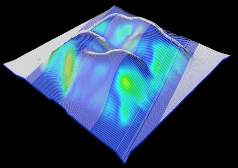
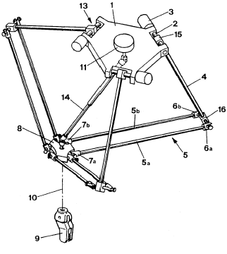
The Delta Robot is a pretty nifty parallel robot (multiple serial kinematic chains connect the end effector to the base) that provides 3 translational degrees of freedom (DOF). To analyze whether it would be a feasible manipulator for use in a microassembly work cell, with the help of Prof. Rick Groff, I worked through the forward and inverse kinematics, and generated a 3D plot of the workspace. The process included learning a little about Pluecker coordinates because they turn out to make the kinematics computations simpler thanks to a nice point/line duality explained in this short summary. The matlab files below are essentially a translation of the BASIC code provided by Prof. Zsombor-Murray in his paper on the Delta Robot kinematics. Please feel free to use the files below in your work if you find them helpful.